
How to Change Units in AutoCAD

AutoCAD 2022 is the latest release of the ultra-popular design software that replaces traditional paper drafting with a powerful digital toolkit.
First time using the platform? Here’s a brief guide showing how to change your default AutoCAD units and streamline your workflow.
Why Use Units?
As an isolated piece of information, a unitless drawing will work just as well and prevent possible confusion. Hardly any information stands on its own, however, in these days of hyperconnectivity and multidisciplinary teamwork.
In many cases, external drawings will be inserted as blocks, and it is paramount that their scale aligns. Unit settings also apply to imported point cloud data and linked xrefs (external references often used as overlays).
Without proper matching, drawings may fall outside the workspace limits. Visual effects such as dash-dot lines, material textures, and hatched areas will also be affected.
In the same vein, it is vital that dimensions appear properly attuned to the drawing, especially in architectural layouts.
Whether you are involved in architectural, civil, mechanical, or electrical design, it is always best to configure your unit settings carefully.
Let’s jump right in.
Setting Default Units
AutoCAD drawings are unitless until a measurement system is applied. It’s easiest to do this by using a template.
Step 1: Click the red “A” on the upper left corner of the page.
Step 2: Choose New → Drawing.
Step 3: In the Files of type dropdown list, select Drawing Template (*.dwt). A folder will open that shows the AutoCAD templates.
Step 4: Now, select either acad.dwt for a drawing with imperial units (inches, feet, etc.) or acadiso.dwt for metric units.
Pro Tip: Save acad.dwt as a drawing named Imperial.dwg and acadiso.dwt as Metric.dwg and load those for future projects instead to prevent any confusion.
Changing AutoCAD Units
Available working units in AutoCAD range from angstroms to light years and parsecs. Here’s another way to change measurement units for your projects:
Step 1: Open the application menu by clicking the “A” icon.
Step 2: Select Drawing Utilities → Units. This opens the Drawing Units popup window. Alternatively, type UN or Units in the command line and hit Enter.
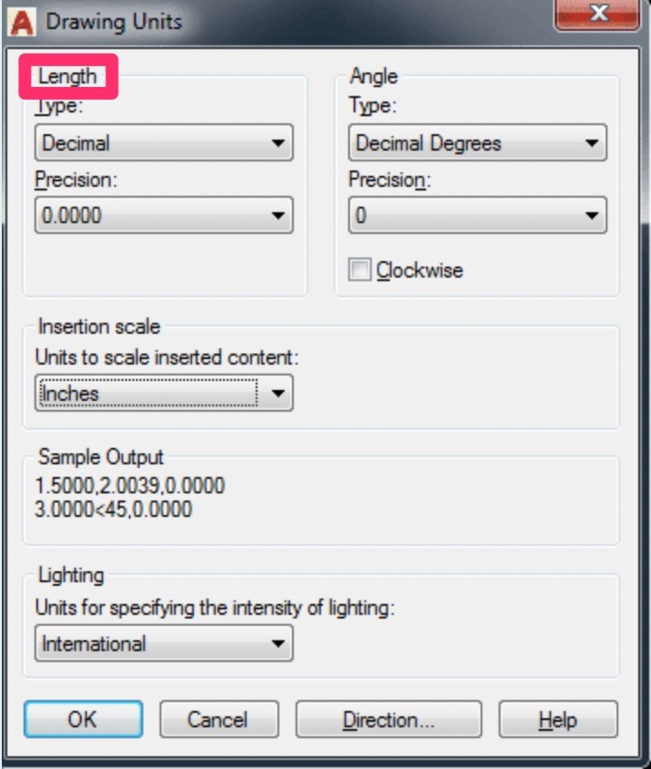
Step 3: Under Length, choose the correct unit type.
The most common notations are:
- Decimal for metric (a value of 38.5 is written as 38.5000).
- Engineering for imperial (a value of 38.5 is written as 3’–2.5”).
- Architectural uses proper imperial notation (38.5 is output as 3’–2½”).
- Scientific is used mostly by mathematicians and engineers to simplify operations with large numbers (38.5 reads as 8500E+01).
- Fractional uses the metric system with decimals written as fractions (38.5 becomes 38½).
Step 4: Set the precision to the number of decimal places or the fractional size you prefer to display.
Step 5: Set a different angle type if necessary. The options are:
- Deg-Min-Sec or DMS (for example, degrees/minutes/seconds). A system for writing fractional angles based on the division of one degree in 60 minutes of 60 seconds each.
- Grads. Gradians, based on a division of 90 degrees into 100 gradians.
- Radians. A display of angular measurements in the form of 180/π
- Decimal Degrees.
- Surveyor’s Units.
Step 6: Under Insertion scale, select a unit to be applied automatically to imported content.
Step 7: Press OK.
Note: U.S. Survey Feet is a historical unit two parts-per-million larger than the standard foot defined by the 1959 International Yard and Pound Agreement. It is used only for mapping purposes in the United States.
Add Units to the Workspace
To obtain one-click access to Units settings, add a widget to the lower bar of the workspace.
Here’s how to do that:
Step 1: Click the “hamburger” or “three-line” button with stacked horizontal lines on the bottom-right corner of the page.
Step 2: Check Units.
Success! This toggles the Units option’s visibility as a widget on the lower taskbar.
Convert Units for Inserted Drawings
When receiving drawings from fellow students, colleagues, consultants, or clients, you will often find that they have set their units to deviate from the ones used in your own work.
If so, it is important to know that in AutoCAD, a drawing’s units are stored under the INSUNITS system variable. They can be altered by typing INSUNITS in the command prompt and entering one of the following values:
- 0 = Unitless
- 1 = Inches
- 4 = Millimeters
- 6 = Meters
There are also a few register values you can enter in AutoCAD for automatic scaling on import:
- INSUNITSDEFSOURCE overrules the INSUNITS value of the imported block if that one was set to 0 (unitless).
- INSUNITSDEFTARGET overrules the INSUNITS value of the drawing if it was set to 0.
These can also be accessed from Options → User Preferences → Insertion Scale. Don’t worry, we’re just altering some basic variables. It’s not like we’re learning how to reverse a string in Python.
Pro Tip: As part of the full version of AutoCAD, the SYSVDLG command opens the System Variables dialog. This is an invaluable resource from which you can access all parameters of the system.
Here’s how to import external drawings at the same scale as the original drawing:
Step 1: From the Home tab → Blocks panel, click Insert to see a gallery of drawings.
(Alternatively, type I or –INSERT in the command prompt.)
Type CLASSICINSERT instead to access the classic Insert dialog box.
Step 2: By using the dialog you have opened, units can be specified. First, click Browse and select the .dwg file to be inserted.
Step 3: Under Insertion Point, uncheck Specify On-screen and leave the X, Y, and Z coordinates set at 0 so they match other objects in the drawing.
Step 4: Make sure Explode is checked.
Step 5: Under Block Unit, ensure that the Unit setting is correct and that Factor is set at 1 for the correct conversion factor.
Step 6: Hit OK.
The same procedure applies when you are using the Attach External Reference dialog after entering the xref command.
DWGUnits
Another way to convert drawing units when inserting is by using the –DWGUNITS command:
Step 1: Type –DWGUNITS (mind the dash) and hit Enter.
Step 2: The system will ask for a Unit for length (1. inch, 2. feet, 3. mm, etc.). Enter the corresponding number and hit Enter.
Step 3: Do the same for the Linear display format (1. Scientific, 2. Decimal, 3. Architectural, etc.)
Step 4: AutoCAD will ask a number of yes/no questions. The following values are most commonly used:
- Scale objects from other drawings upon insert — Yes
- Match INSUNITS to drawing units — Yes
- Scale objects in current drawing to reflect change in units — No
- Include objects in Paper Space — Yes
Step 5: Validate the newly installed unit settings by choosing Zoom Extents from the navigational menu on the right.
Step 6: Look at an existing dimension or draw one if there aren’t any. The changes in dimensions should now be reflected in the drawing.
Final Note
Sometimes, it is necessary to manually resize objects with the Scale command. Here are some useful conversion factors:
- Inches to millimeters = 25.4
- Millimeters to inches = 0.0393701
- Feet to millimeters = 304.8
- Millimeters to feet = 0.00328084
There it is — you are now able to set up your drawing with the correct unit settings, either manually, by using a template, or by importing blocks. We have even touched on learning to code in CAD. Your digital designs will never be measured with double standards again.
Looking to learn about basic and advanced design in AutoCAD? Sign up to get some high-quality online tutoring at 24HourAnswers today.