Mechanical Engineering
Homework Help & Tutoring
We offer an array of different online Mechanical Engineering tutors, all of whom are advanced in their fields and highly qualified to instruct you.


Mechanical Engineering
Mechanical engineering combines principles of physics, mathematics and materials science to design and manufacture mechanical systems. Mechanical engineers use their specialized scientific knowledge and problem-solving skills to create impactful machinery for a wide range of industries.
The coursework for college students studying mechanical engineering typically involves advanced math and science principles. If you're struggling with the mechanical engineering concepts you're learning, our highly qualified tutors can help you understand them on a deeper level. You can come to us 24/7 for help with virtually any type of mechanical engineering topic or assignment. We'll help you expand your knowledge and find the solutions you need.
Online Mechanical Engineering Tutors
Our mechanical engineering tutors provide homework help and tutoring sessions on many mechanical engineering topics. You'll get personalized support with step-by-step guidance to help you overcome your academic challenges.
Tutoring Sessions
Scheduling a live, online tutoring session with one of our mechanical engineering tutors is the best way to get comprehensive guidance on difficult concepts. You can take advantage of our state-of-the-art whiteboard platform that offers video, audio, file upload support and desktop sharing for a productive tutoring session.
We recommend uploading relevant documents like study materials and old quizzes ahead of time — doing so will give your tutor the chance to review the materials so you can get the most out of your session. They'll tailor their instruction to ensure it readily relates to what you're learning.
Homework Help
You can also come to us for mechanical engineering homework help. If you're tackling a challenging problem or assignment, our expert mechanical engineering tutors are here to assist you. They'll help you better understand the question and concepts involved so you can create an original solution.
If you need something more immediate, we have a Homework Library of solved problems you can search. Our Homework Library includes detailed examples and explanations to help you understand the process of going from question to answer.
Mechanical Engineering Topics
In addition to advanced math and science coursework, our expert tutors can help you with many different mechanical engineering topics, including:
- Manufacturing engineering: Manufacturing engineering is concerned with the development and optimization of machines, tools and manufacturing techniques.
- Thermal engineering: Thermal engineering deals with heat energy and transfer in mechanical systems.
- Acoustical engineering: Acoustical engineering deals with the design, analysis and control of vibration and sound.
- Design engineering: Design engineering uses mechanical engineering principles to improve machine design.
Why Choose 24HourAnswers for Mechanical Engineering Help?
At 24HourAnswers, our goal is to help you succeed. We have a meticulous screening process to ensure we bring on only the best tutors. Many of our mechanical engineering tutors have advanced degrees and experience, including Ph.D.s and positions at top companies and universities. While other online tutoring services employ mainly college students, 24HourAnswers gives you unique access to highly qualified mechanical engineering professionals.
You can request a tutoring session or homework help from us 24/7. Our tutors respond to student queries as soon as possible, often in just minutes. You'll receive their quote based on your unique needs, and you're free to discuss the price with them. You can also specify your budget in advance when submitting your request.
We offer fair pricing with no minimum payments or monthly fees. You won't have to pay anything until you're sure our service is right for you.
Find an Online Tutor for Mechanical Engineering
24HourAnswers is your go-to source for tutoring in mechanical engineering. Since our company began in 2005, we've helped over 1 million students around the globe. We have a student satisfaction rating of 99.5%, and we are A+ rated by the Better Business Bureau.
Get the help you need today and request a tutoring session or homework help for your mechanical engineering assignments. All you have to do is submit your request, upload any relevant documents, choose a delivery date and create an account if you don't already have one. The process takes just a few minutes to complete.
Sample Problems and Solutions
Question 1:
Since a refrigeration system operates more efficiently when the condensing temperature is low, evaluate the possibility of cooling the condenser cooling water of the refrigeration system with another refrigeration system. Will the combined performance of the two systems be better, the same, or worse than one individual system? Explain why.
The answer is the combined performance will be worse than one individual system. The following is proof.
Consider the two systems as described above:
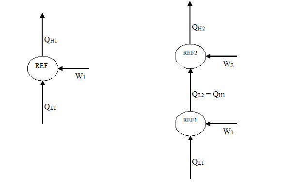
where QL and QH refer to the heat removed from cooled space and rejected to warm space, respectively. Note that in the combined system, QL2 = QH1 because the heat rejected from REF1 (QH1) is received as the cooling load for REF2 (QL2).
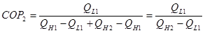
The efficiency of refrigerator is normally defined through the coefficient of performance (COP):
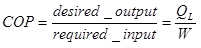
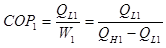
So, we can write the COP for the single system as:
 (1)
(1)
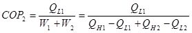
The COP for the combined system is:
 (2)
(2)
Note that we have the same desired output as single system QL1. But QL2 = QH1, substitute into 2:
 (3)
(3)
We see that because:
QH2 = QH1 + QW2
And so:
QH2> QH1
By comparing equations 1 and 3, we derrive that COP2 < COP1
REFERENCES
Rajput, R.K., 2000. Thermal Engineering. S.Chand Publishers.
Question 2:
A two-stage ammonia system using flash-gas removal and intercooling operates on the cycle shown below. The condensing temperature is 35 degrees C. The saturation temperature of the intermediate-temperature evaporator is 0 degrees C, and its capacity is 150KW. The saturation temperature of the low-temperature evaporator is -40 degrees C, and its capacity is 250KW. What is the rate of refrigerant compressed by the high-stage compressor?
Add an adiabatic/isentropic efficiency of the compressors of 85% and THEN solve the problem. Should your answer be higher or lower than the one given in the book?
Given:
T5 = 35oCT3 = 0oCT1 = -40oCQ1 = 150 kWQ2 = 250 kW = 85% = 0.85
Solution:
Find specific enthalpies at all points shown on the above diagram, using saturated and superheated ammonia vapor tables.
Point 5. Here the ammonia is saturated liquid. From saturated vapor table at 35oC we get the enthalpy, and pressure, respectively:
h5 = hf = 346.8 kJ/kgP5 = 1350.4 kPa
Point 6. The throttle valve is isenthalpic, so the enthalpy is
h6 = h5= 346.8 kJ/kg
Point 3. Here the ammonia is saturated gas. From saturated vapor table at 0oC we get the enthalpy, entropy, and pressure respectively:
h3 = hg = 1442.2 kJ/kg
s3 = sg = 5.3309 kJ/(kg*K)
P3 = 429.6 kPa
Point 7. Here the ammonia is saturated liquid. From saturated vapor table at 0oC we get the enthalpy
h7 = hf = 180.36 kJ/kg
Point 8. The throttle valve is isenthalpic, so the enthalpy is
h8 = h7 = 180.36 kJ/kg
Point 1. Here the ammonia is saturated gas. From saturated vapor table at -40oC we get the enthalpy and entropy, respectively:
h1 = hg = 1388.8 kJ/kg
s1 = sg = 5.9569 kJ/(kg*K)
Point 2. The high-stage compressor is isentropic so the entropy at point 2 is
s2 = s1 = 5.9569 kJ/(kg*K)
The pressure at point 2 is
P2 = P3 = 429.6 kPa
Now, from the superheated vapor table and using linear interpolation between pressures 400 kPa and 500 kPa we get for pressure 429.6 kPa near entropy 5.9569 kJ/(kg*K):
h = 1636.7+(1633.1-1636.7)*(429.6-400)/(500-400) = 1635.6 kJ/kg
at
s = 5.9907+(5.8744-5.9907)*(429.6-400)/(500-400) = 5.9563 kJ/(kg*K)
and
h = 1682.8+(1679.8-1682.8)*(429.6-400)/(500-400) = 1681.9 kJ/kg
at
s = 6.1179+(6.0031-6.1179)*(429.6-400)/(500-400) = 6.0839 kJ/(kg*K)
Now using linear interpolation, we find enthalpy at point 2 for an ideal low-stage compressor
h2 = 1635.6+(1681.9-1635.6)*(5.9569-5.9563)/(6.0839-5.9563) = 1635.8 kJ/kg
Let h2rfeal be the specific enthalpy at point 2 for real low-stage compressor. Then its isentropic efficiency is given by
= (h2real - h1)/(h2 - h1)
From which we get
h2real = h1 + *(h2 - h1)
Which is
h2real = 1388.8+0.85*(1635.8-1388.8) = 1598.8 kJ/kg
Point 4. The low-stage compressor is isentropic so the entropy at point 4 is
s4 = s3 = 5.3309 kJ/(kg*K)
The pressure at point 4 is
P4 = P5 = 1350.4 kPa = 1.3504 MPa
Now from the superheated vapor table using a linear interpolation between pressures 1.2 MPa and 1.4 MPa we get for pressure 1.3504 MPa near entropy 5.3309 kJ/(kg*K):
h = 1606.8+(1598.8-1606.8)*(1.3504-1.2)/(1.4-1.2) = 1600.8 kJ/kg
at
s = 5.3916+(5.2994-5.3916)*(1.3504-1.2)/(1.4-1.2) = 5.3223 kJ/(kg*K)
and
h = 1658.0+(1651.4-1658.0)*(1.3504-1.2)/(1.4-1.2) = 1653.0 kJ/kg
at
s = 5.5325+(5.4443-5.5325)*(1.3504-1.2)/(1.4-1.2) = 5.4662 kJ/(kg*K)
Now, using linear interpolation, we find enthalpy at point 4 for an ideal high-stage compressor
h4 = 1600.8+(1653.0-1600.8)*(5.3309-5.3223)/(5.4662-5.3223) = 1603.9 kJ/kg
Similarly to point 2, we get the enthalpy at point 4 for real high-stage compressor
h4real = h3 + *(h4 - h3)
Which is
h4real = 1442.2+0.85*(1603.9-1442.2) = 1579.64 kJ/kg
To find the mass flow rates of refrigerant through intermediate-temperature and low-temperature evaporators, respectively:
m1 = Q1/(h3 - h6) = 150/(1442.2-346.8) = 0.13693 kg/s
m2 = Q2/(h1 - h8) = 250/(1388.8-180.36) = 0.20688 kg/s
Letting mh be mass flow rate of refrigerant through the high-stage compressors. Then the steady flow energy equation for the intercooler and flash tank is
m2*h2real + (mh - m1)*h6 = m2*h7 + (mh - m1)*h3
Solving for mh gives the answer
mh = m1 + m2*(h2real - h7)/(h3 - h6)
Which is
mh = 0.13693+0.20688*(1598.8-180.36)/(1442.2-346.8) = 0.4048 kg/s
This is lower than the former value 0.4118 kg/s for ideal compressors
REFERENCES
Rajput, R.K., 2000. Thermal Engineering. S.Chand Publishers.
Question 3:
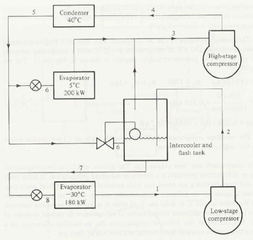
A R22 flash-gas removal system has a capacity of 180KW at an evaporating temperature of -30 degrees C when the condensing pressure is 1500KPa. Compute the power requirement for a system with a single compressor. Compute the total power required by the two compressors in the system where there is no intercooling but there is flash-gas removal at 600KPa.
Add an adiabatic/isentropic efficiency of the compressors of 85% and THEN solve the problem. Should your answer be higher or lower than the one given in the book?
(b) Given:
Qin = 180 kW
t1 = -30oC
P2 = P4 = P5 = 1500 kPa
P3 = P6 = P7 = 600 kPa
 = 85% = 0.85
Solution:
Find the specific enthalpies at all points on the Figure 16-17.
From saturated table we have for saturated liquid near 1500 kPa
P hf
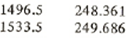
Now using linear interpolation find the specific enthalpy at point 5
h5 = hf = 248.361+(249.686-248.361)*(1500-1496.5)/(1533.5-1496.5) = 248.486 kJ/kg
The throttle valve at point 6 is isenthalpic, so the specific enthalpy at point 6 is
h6 = h5 = 248.486 kJ/kg
From saturated table at -30oC we get the specific enthalpy and entropy at point 1 for saturated vapor
h1 = hg = 393.138 kJ/kg
s1 = sg = 1.80329 kJ/(kgK)
The saturated table gives near 600 kPa


Using linear interpolation we get for 600 kPa:
t = 5+(6-5)*(600-583.78)/(602.28-583.78) = 5.87675oC
hg = 407.143+(407.489-407.143)*(600-583.78)/(602.28-583.78) = 407.446 kJ/kg
hf = 205.899+(207.089-205.899)*(600-583.78)/(602.28-583.78) = 206.942 kJ/kg
sg = 1.74463+(1.74324-1.74463)*(600-583.78)/(602.28-583.78) = 1.74341 J(kgK)
Now we get he enthalpy and entropy at point 3, and enthalpy at point 7:
h3 = hg = 407.446 kJ/kg
s3 = sg = 1.74341 J(kgK)
h7 = hf = 206.942 kJ/kg
The throttle valve at point 8 is isenthalpic, so the specific enthalpy at point 8 is
h8 = h7 = 206.942 kJ/kg
The flash-gas compressor is isentropic, so the specific entropy at point 4 is
s4 = s3 = 1.74341 kJ/(kgK)
From saturated table at pressure 1500 kPa we find the saturation temperature 39oC. Now from superheated table using columns with saturation temperatures 38oC and 40oC find the enthalpies and entropies at column with saturated temperature 39oC near the entropy 1.74341 kJ/(kgK):
h = (427.155+425.871)/2 = 426.513 at s = (1.7365+1.7287)/2 = 1.73260
h = (431.568+430.374)/2 = 430.971 at s = (1.7501+1.7426)/2 = 1.74635
Now using liner interpolation find the specific enthalpy at point 4 for ideal flash-gas compressor
h4 = 426.513+(430.971-426.513)*(1.74341-1.73260)/(1.74635-1.73260) = 430.018 kJ/kg
Let h4rfeal be specific enthalpy at point 4 for real flash-gas compressor. Then its isentropic efficiency is given by
= (h4real - h3)/(h4 - h3)
From which we get
h4real = h3 + *(h4 - h3), which is
h4real = 407.446+0.85*(430.018-407.446) = 426.63 kJ/kg
The evaporator compressor is isentropic, so the specific entropy at point 2 is
s2 = s1 = 1.80329 kJ/(kgK)
Similarly to the above from the superheated table we get near the entropy 1.80329 kJ/(kgK):
h = (448.703+447.771)/2 = 448.237 at s = (1.8008+1.7940)/2 = 1.7974
h = (452.901+452.019)/2 = 452.46 at s = (1.8127+1.8061)/2 = 1.8094
Now we can get the enthalpy at point 2 for an ideal evaporator compressor
h2 = 448.237+(452.46-448.237)*(1.80329-1.7974)/(1.8094-1.7974) = 450.301 kJ/kg
The specific enthalpy at point 2 for a real evaporator compressor is given by
h2real = h1 + *(h2 - h1) which is
h2real = 393.138+ 0.85*(450.301-393.138) = 441.73 kJ/kg
Let m1 and m2 be mass flow through evaporator and flash-gas compressors, respectively. The mass flow m1 is given by
m1 = Qin/(h1 - h8) = 180/(393.138-206.942) = 0.96672 kg/s
The steady flow energy equation for points 3-6-7 gives
(m1 + m2)*h6 = m1*h7 + m2*h3
From which we get m2
m2 = m1*(h6-h7)/(h3-h6) which is
m2 = 0.96672*(248.486-206.942)/(407.446-248.486) = 0.25265 kg/s
The power required by the evaporator and flash-gas compressors are given by, respectively:
W1 = m1*(h2real - h1)
W2 = m2*(h4real - h3)
Now we can find the total power required by two compressors
W = W1 + W2 = m1*(h2real - h1) + m2*(h4real - h3)
which is
W = 0.96672*(441.73-393.138)+0.25265*(426.63-407.446) = 51.82 kW
This is lower than the former value 60.96 kW for ideal compressors.
REFERENCES
Rajput, R.K., 2000. Thermal Engineering. S.Chand Publishers.
Question 4:
In a R22 refrigeration system the capacity is 180KW at a temperature of -30 deg C. The vapour from the evaporator is pumped by one compressor to the condensing pressure of 1500KPa. Later the system is revised to two-stage compression operating on a cycle with intercooling but no removal of flash gas at 600KPa. Calculate the power required from a single compressor in the original system? Calculate the power required from two compressors in the revised system?
(a) Given:
Qin = 180 kW
t1 = -30oC
P2 = 1500 kPa
Solution:

Find the specific enthalpies at all points in the above original one evaporator - one compressor refrigeration system, using Table A-6 for saturated and Table A-7 for superheated Refrigerant 22
From the saturated table we have for saturated liquid near 1500 kPa
P hf

Using linear interpolation find the specific enthalpy at point 3:
h3 = hf = 248.361+(249.686-248.361)*(1500-1496.5)/(1533.5-1496.5) = 248.486 kJ/kg
The throttle valve is isenthalpic, so the specific enthalpy at point 4 is
h4 = h3 = 248.486 kJ/kg
From saturated table at -30oC we get the specific enthalpy and entropy at point 1 for saturated vapor
h1 = hg = 393.138 kJ/kg
s1 = sg = 1.80329 kJ/(kgK)
The compressor is isentropic, so the specific entropy at point 2 is
s2 = s1 = 1.80329 kJ/(kgK)
From the saturated table at pressure 1500 kPa we find the saturation temperature 39oC. Now from the superheated table using columns with saturation temperatures 38oC and 40oC find the enthalpies and entropies at column with saturated temperature 39oC near the entropy 1.80329 kJ/(kgK):
h = (448.703+447.771)/2 = 448.237 for s = (1.8008+1.7940)/2 = 1.7974
h = (452.901+452.019)/2 = 452.460 for s = (1.8127+1.8061)/2 = 1.8094
Now using liner interpolation find the specific enthalpy at point 2
h2 = 448.237+(452.460-448.237)*(1.80329-1.7974)/(1.8094-1.7974) = 450.310 kJ/kg
Find the mass flow rate of refrigerant
m = Qin/(h1 - h4) = 180/(393.138-248.486) = 1.24437 kg/s
Now we can find the power of the compressor required
W = m*(h2 - h1) = 1.24437*(450.310- 393.138) = 71.1 kW
(b) Given:
Qin = 180 kW
t1 = -30oC
P4 = 1500 kPa
P2 = P3 = P6 = 600 kPa
Now find the specific enthalpies at all points in the above figure.
From the saturated table we have for saturated liquid near 1500 kPa
P hf
Now using linear interpolation find the specific enthalpy at point 5
h5 = hf = 248.361+(249.686-248.361)*(1500-1496.5)/(1533.5-1496.5) = 248.486 kJ/kg
The throttle valve is isenthalpic, so the specific enthalpy at points 6 and 7 is
h6 = h7 = h5 = 248.486 kJ/kg
From saturated table at -30oC we get the specific enthalpy and entropy at point 1 for saturated vapor
h1 = hg = 393.138 kJ/kg
s1 = sg = 1.80329 kJ/(kgK)
The low-stage compressor is isentropic, so the specific entropy at point 2 is
s2 = s1 = 1.80329 kJ/(kgK)
The saturated table gives near 600 kPa
![]()
![]()
Using linear interpolation we get for 600 kPa:
t = 5+(6-5)*(600-583.78)/(602.28-583.78) = 5.87675oC
hg = 407.143+(407.489-407.143)*(600-583.78)/(602.28-583.78) = 407.446 kJ/kg
sg = 1.74463+(1.74324-1.74463)*(600-583.78)/(602.28-583.78) = 1.74341 J(kgK)
Now we get he enthalpy and entropy at point 3:
h3 = hg = 407.446 kJ/kg
s3 = sg = 1.74341 J(kgK)
From the superheated table using columns with saturation temperatures 5oC and 10oC find the enthalpies and entropies at column with saturated temperature 5.87675oC near the entropy 1.80329 kJ/(kgK):
h = 425.562+(423.974-425.562)*(5.87675-5)/(10-5) = 425.284
for s = 1.8080+(1.7894-1.8080)*(5.87675-5)/(10-5) = 1.80474
and
h = 429.229+(427.724-429.229)*(5.87675-5)/(10-5) = 428.965
for s = 1.8200+(1.8017-1.8200)*(5.87675-5)/(10-5) = 1.81679
Now using liner interpolation find the specific enthalpy at point 2
h2 = 425.284+(428.965-425.284)*(1.80329-1.80474)/(1.81679-1.80474) = 424.841 kJ/kg
The high-stage compressor is isentropic, so the specific entropy at point 4 is
s4 = s3 = 1.74341 J(kgK)
From the saturated table at pressure 1500 kPa we find the saturation temperature 39oC. Now from the superheated table using columns with saturation temperatures 38oC and 40oC find the enthalpies and entropies at column with saturated temperature 39oC near the entropy 1.74341 kJ/(kgK):
h = (427.155+425.871)/2 = 426.513 at s = (1.7365+1.7287)/2 = 1.73260
h = (431.568+430.374)/2 = 430.971 at s = (1.7501+1.7426)/2 = 1.74635
Now using liner interpolation find the specific enthalpy at point 4
h4 = 426.513+(430.971-426.513)*(1.74341-1.73260)/(1.74635-1.73260) = 430.018 kJ/kg
Let m1 and m2 be mass flow through low-stage and high-stage compressors, respectively.
The mass flow m1 is given by
m1 = Qin/(h1 - h7) = 180/(393.138-248.486) = 1.24437 kg/s
The steady flow energy equation for intercooler gives
(m2 - m1)*h6 + m1*h2 = m2*h3
From which we get m2
m2 = m1*(h2-h5)/(h3-h5)
Which is
m2 = 1.24437*(424.841-248.486)/(407.446-248.486) = 1.38054 kg/s
The powers required by low-stage and high-stage compressors are given by, respectively:
W1 = m1*(h2 - h1)
W2 = m2*(h4 - h3)
Now we can find the total power required by two compressors
W = W1 + W2 = m1*(h2 - h1) + m2*(h4 - h3)
Which is
W = 1.24437*(424.841-393.138) + 1.38054*(430.018-407.446) = 70.6 kW
Question 5:
A refrigeration system using R22 is to have a refrigerating capacity of 80KW. The cycle is standard vapour-compression cycle in which the evaporating temperature is -8 deg C and the condensing temperature is 42 deg C.
Determine the volume flow of refrigerant measured in cubic meters per second at the inlet to the compressor.
Calculate the power required by the compressor.
At the entrance to the evaporator what is the fraction of vapour in the mixture expressed both on a mass basis and a volume basis?
Given:
Qin = 40 kW
T1 = -8oC
T3 = 42oC
Solution:
Refer to above diagram of the refrigeration system, and find the specific enthalpies at all points.
From the saturated vapor table at 42oC find the specific enthalpy at point 3 for saturated liquid
h3 = hf = 252.352 kJ/kg
The throttle valve is isenthalpic, so the same specific enthalpy is at point 4
h4 = h3 = 252.352 kJ/kg
From the saturated vapor table at -8oC we get the specific enthalpy, specific entropy, specific volume, and pressure at point 1 for saturated vapor, respectively:
h1 = hg = 402.341 kJ/kg
s1 = sg = 1.76394 kJ/(kgK)
v1 = vg = 61.0958 L/kg = 0.0610958 m3/kg
P1 = 380.06 kPa
The compressor is isentropic, so the specific entropy at point 2 is
s2 = s1 = 1.76394 kJ/(kgK)
From the superheated vapor table at saturation temperature 42oC we have the enthalpy and entropy near the entropy 1.76394 kJ/(kgK):
h s
Using linear interpolation we get the specific enthalpy at point 2
h2 = 438.062+(442.449-438.062)*(1.76394-1.7618)/(1.7747-1.7618) = 438.790 kJ/kg
Now we get:
(a) The specific heat received by evaporator is given by
qin = h1 - h4 = 402.341-252.352 = 149.989 kJ/kg
So the mass flow of refrigerant is
M = Qin/qin = 40/149.989 = 0.266686 kg/s
Now we can get the volume flow rate at the inlet of compressor
V = m*v1 = 0.266686*0.0610958 = 0.0162934 or 0.0163 m3/s
(b) Find specific power of the compressor
w = w = h2 - h1 = 438.790-402.341 = 36.4490 kJ/kg
Now we can find power of the compressor
W = w*M = 36.4490*0.266686 = 9.72044 9.72 kW
(c) The pressure at point 4 is
P4 = P1 = 380.06 kPa
From the saturated vapor table at 380.06 kPa we get the specific enthalpies and specific volumes for saturated liquid and vapor, respectively:
hf = 190.718 kJ/kg
hg = 402.341 kJ/kg
vf = 0.76253 L/kg
vg = 61.0958 L/kg
The fraction of vapor in the mixture at the entrance of the evaporator, at point 4, expressed on a mass basis is given by:
x4m = (h4 - hf)/(hg - hf) = (252.352-190.718)/(402.341-190.718) = 0.29124 or 0.291
(d) Find specific volume at point 4
v4 = (1 - x4m)*vf + x4m*vg = (1-0.29124)*0.76253+0.29124*61.0958 = 18.3340 L/kg
The fraction of vapor in the mixture at the entrance of the evaporator expressed on a volume basis is given by:
x4v = (1/v4-1/vf)/(1/g-1/vf) = (1/8.3340-1/0.76253)/(1/61.0958-1/0.76253) = 0.971
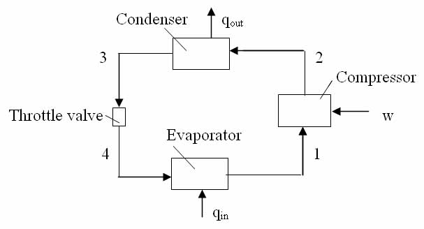
Question 6:
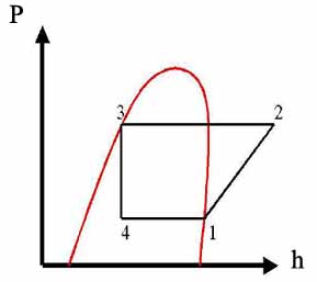
If in a standard vapor compression cycle using R22 refrigerant the evaporating temperature is -5 deg C and the condensing temperature is 30 deg C, sketch the cycle on pressure-enthalpy coordinates and calculate the work of compression, the refrigerating effect, and the heat rejected in the condenser in KJ/Kg and the corresponding COP as well.
Given:
T1 = -5oC
T3 = 30oC
Solution:
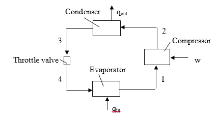
The diagram of the vapor-compression cycle is shown above, where: P1=P4; P2=P3
The corresponding cycle on pressure-enthalpy coordinates is drawn below
Find enthalpies at all points using Table A-6 for saturated Refrigerant 22 and Table A-7 for superheated Refrigerant 22
From the saturated vapor table at 30oC we get the specific enthalpy and pressure, respectively, at point 3 for saturated liquid:
h3 = hf = 236.664 kJ/kg
P3 = 1191.9 kPa
Since the throttle valve is isenthalpic the specific enthalpy at point 4 is
h4 = h3 = 236.664 kJ/kg
From saturated vapor table at -5oC we get the specific enthalpy and entropy at point 1 for saturated vapor:
h1 = hg = 403.496 kJ/kg
s1 = sg = 1.75928 kJ/(kgK)
Since the compressor is isentropic the specific entropy at point 2 is
s2 = s1 = 1.75928 kJ/(kgK)
The pressure at point 2 is
P2 = P3 = 1191.9 kPa
From superheated vapor table at saturation temperature 30oC we have the enthalpy and entropy near entropy 1.75928 kJ/(kgK):
h s
Using linear interpolation we get the specific enthalpy at point 2
h2 = 427.378+(431.549-427.378)*(1.75928-1.7534)/(1.7664-1.7534) = 429.265 kJ/kg
Now we get:
(a) The work of compression is given by
w = h2 - h1
which is
w = 429.265-403.496 = 25.769 25.8 kJ/kg
(b) The refrigerating effect is given by
qin = h1 - h4
which is
qin = 403.496-236.664 = 166.832 167 kJ/kg
(c) The heat rejected in the condenser is given by
qout = h2 - h3
which is
qout = 429.265-236.664 = 192.601 193 kJ/kg
(d) The coefficient of performance is given by
COP = qin/w
Which is
COP = 166.832/25.769 = 6.47
REFERENCES
Rajput, R.K., 2000. Thermal Engineering. S.Chand Publishers.
Sample Problems and Solutions in Advanced Dynamics
Question 1:
Derive the response of viscously damped SDOF system to the force F(t) by means of the convolution integral and plot the response for the system.
Solution
The equation of motion of a single degree of freedom system is 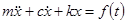
Natural frequency: 
Damping ratio: 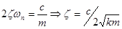
The impulse response function 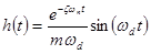 when
when 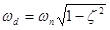
Given force 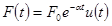 ,
,
The response of the system is
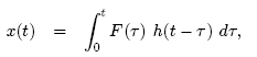
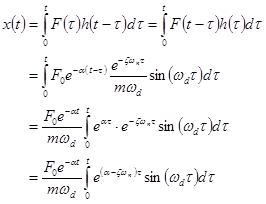
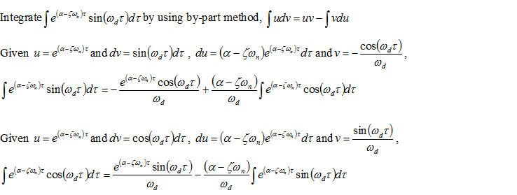
Thus,
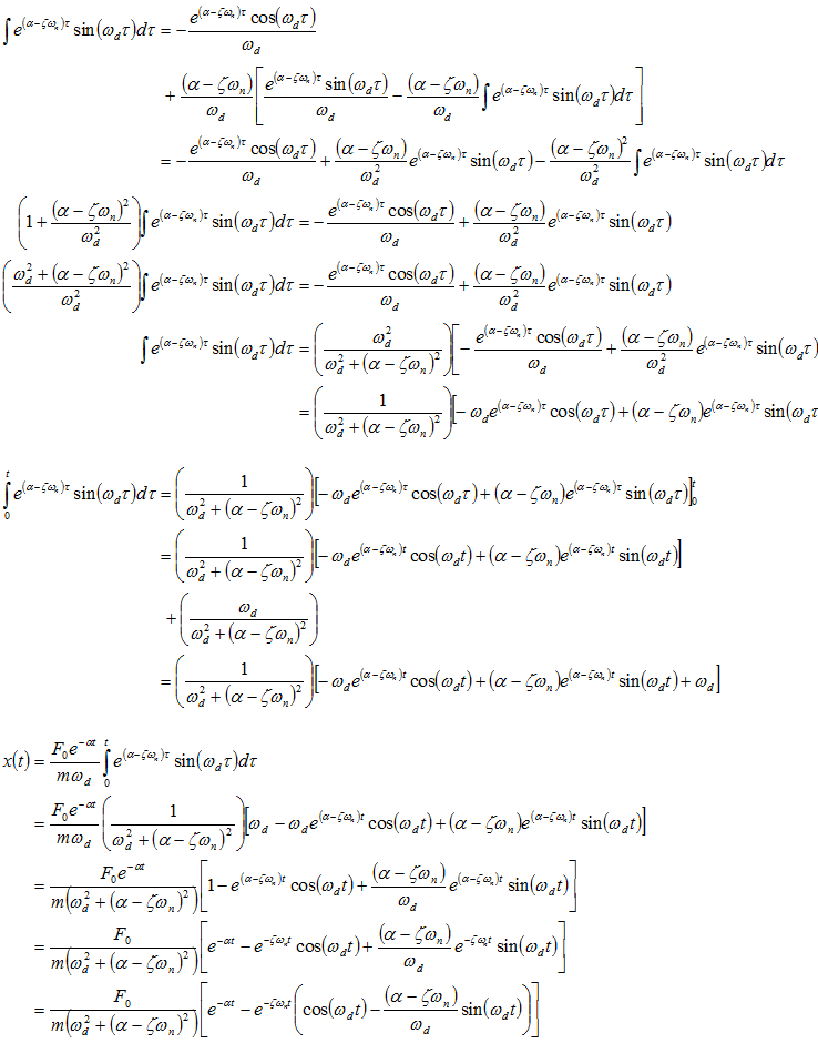
The response of the system with given force is 
Question 2
Plot the response of a viscously damped force free system.
(a) Given:
x(0) = 2 cm
x'(0) = 0
ωn = 5 rad/s = frequency of undamped oscillation
ς = 0.1
Solution:
We have the differential equation for oscillations
x'' + 2ςωnx' + ωn2x = 0 (1)
The general solution is given by
x(t) = Xo exp(-ςωnt) cos(ωn√(1- ς2) t + φ) (2)
Differentiating gives
x'(t) = -Xoωn exp(ςωn-t) [ς cos(ωn√(1- ς2) t + φ) + √(1- ς2) sin(ωn √(1- ς2) t + φ)]
Substituting the initial conditions gives:
x'(0) = -Xoωn(ς cos φ + √(1- ς2 sin φ) = 0
x(0) = Xo cos φ = 2
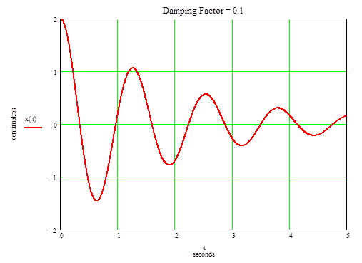
From which we get:
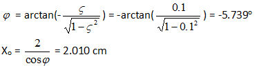
The graph of x(t) for damping factor =0.1 is drawn below
(b) Now the formula (2) in part (a) gives the general solution for ς = 1
x(t) = (Xo cos φ) exp(-ωnt)
Substituting the initial conditions gives the system of equations:
x'(0) = -Xo ωn cos φ = 0
x(0) = Xo cos φ = 2
From the first equation we get
cos φ = 0
Substituting it into the second equation we get that the Xo is infinitely large. So the system of equations has no physical solution for the given initial conditions
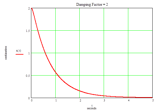
(c) Now the differential equation (2) in part (a) gives for ς = 2 and ωn = 5
x'' + 20x' + 25x = 0
Find the solution in form
x = exp(-pt)
Put it into the above equation and get the equation for p
p2 - 20p + 25 = 0
Solving for p gives
p = 10± √(102-25) = 10 ± √75
Thus the general solution is
x(t) = X1exp[-(10 + √75)t] + X2exp[-(10 - √75)t]
The initial conditions give the system of equations:
x'(0) = -X1(10 + √75) - X2(10 - √75) = 0
x(0) = X1 + X2 = 2
Solving for X1 and X2 gives:
X1 = -0.155
X2 = 2.15
Thus the equation is
x(t) = -0.155exp[-(10 + √75)t] + 2.15exp[-(10 - √75)t]
The graph is drawn below
 n
n
References
Meirovitch, L., 2010, Fundamentals of Vibrations, Waveland Pr Inc
Sample Problems in Mechanical Engineering
Traditionally mechanical engineering is considered to be made of three mainstream engineering aspects: manufacturing engineering, thermal engineering and design engineering. To excel in the domain a thorough knowledge of all of these is essential. A practicing mechanical engineer must solve many problems every day in all these subdomains.
Shaper Cutting Time
Consider a shaper machine is working to smooth a surface plate of length 400mm. Assume the feed of the shaper tool is 2mm/stroke and it is working at a speed of 50 strokes per minute. Determine the time it takes for the shaper to complete machining of the surface of the shaper machine.
The length of the travel needed on the job, Lw is 400mm
Assuming a reasonable approach (A) and overrun (O) as 2 mm each, the length of cut required for shaper machine is Lw+A+O = 400 + 2+ 2 = 404 mm.
The feed of the shaper (So) is 2mm/stroke
The speed of the shaper is (Ns) = 50 strokes/minute, hence the time it takes to complete the cutting process = (Lw+A+O)/Ns*So = 404/2*50 = 4.04 minutes.
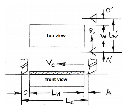
Milling Cutting Time Calculation
Determine the milling time required for milling a rectangular plate of length 100mm, width 50mm by a helical fluted plain HSS milling cutter of diameter 60mm and length 75mm and 6 teeth.
Assume A = O = 5mm, Vc = 40m/min and So = 0.1mm/teeth.
Cutting time Tc = Length of travel (Lc)/Table Feed (Sm)
Length of travel (Lc) = Length of work piece (Lw) + Approach (A) + Overrun (O) + (1/2 x Diameter of the rod)
Table feed(Sm) = So x Zc x N
So = Feed per teeth
Zc = Number of teeth on the cutter
N = Speed of the cutter
Lc = 100mm + 5mm + 5mm + 30mm = 140mm
Sm = 0.1 x 6 x N
N = (1000 x Vc)/(∏ x Dc) = (1000 x 40)/(∏ x 60) = 212.31rpm or ~213rpm
Sm = 0.1 x 6 x 213 = 127.8mm/min
Hence the Cutting time = Lc/Sm = 140/127.88 = 1.09minutes.
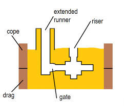
Casting and Metal Flow Problems
Consider the case of a metal mold with a sprue length of 20cm and a cross sectional area at the base of the sprue of 2.5 cm2. If the sprue feeds a horizontal runner leading into a mold cavity whose volume is 1560 cubic centimeter. Determine
- a) the velocity of the molten metal at the base of the sprue;
- b) volume flow rate of the molten metal; and
- c) the time it takes to fill the mold.
For determining the flow rate of the molten metal at the bottom of the sprue pin, Bernoulli’s principle is required. As per Bernoulli’s principle the pressure at the top of the sprue should be converted to the velocity at the bottom of the sprue, so it will be given by the equation:
V = sqrt (2*g*h), where h is the height of the sprue, V is the velocity of the molten metal at the bottom of the sprue,
So in the given problem
- A) Flow velocity of the molten metal, V = sqrt (2*9.81*100*20) = 198.1 cm/s
- B) The flow rate of the molten metal at the bottom of the sprue pin is given by Q = A * V
Where A is the area of cross section of the sprue pin and V is the velocity of the molten metal,
dQ/dt = 2.5 * 198.1 = 495.25 cubic centimeters/s.
- C) Time it takes to fill the mold = Q’/(dQ/dt) = 1560/495.25 = 3.15 seconds
Thermal Engineering
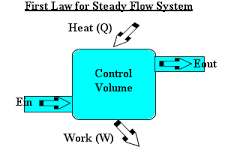
Steady flow Energy Equation (first law of thermodynamics) and the principle of energy conservation
0.5 kg/s of fluid flows in a steady state process. The properties of fluid at the entrance are measured as
p1 = 1.4bar, and the density of the fluid is 2.5kg/m3.
Ui = 920kJ/kg while at exit the properties are P2 = 5.6bar, density = 5kg/m3, U2 = 720KJ/kg.
The velocity at entrance is 200m/s, while at exit it is 180m/s. It rejects 60KW of heat and raises through 60m during the flow process. Determine the change of enthalpy as well as the work done during the process.
The key to the solution is the fact that the total energy remains constant during the process.
Mass flow rate of fluid in the process = mf = 0.5kg/s
Pressure at the inlet to the process = 1.4bar
Density of the fluid = 2.5kg/m3
Initial internal energy of the fluid = 920KJ/kg
Final pressure of the fluid = 5.6bar
Final density at the exit = 5kg/m3
Final internal energy of the fluid =720kJ/kg
Velocity of the fluid at the entrance = 200m/s
Velocity of the fluid at the exit = 180m/s
The amount of the heat given to the fluid during the process = 60KW
The rise in height of the fluid during the process = 60m
Enthalpy change during the process (h2-h1) = ∆(U2-U1) + ∆PV
Therefore, ∆PV = p2/ρ2 – p1/ρ1.
Specific enthalpy change = (720 - 920) x 103 + (5.6/5 - 1.4/2.5) x 105 = -144KJ/kg
Hence Enthalpy change = ∆H = mf x (h2-h1) = 0.5 x (-144) = -72 KJ/s
The steady flow energy equation (SFEE) can be applied as:
SFEE - Q - WS = mf [(h2 – h1) + ½( V22 –V12) + g(Z2 –Z1)]
60 x 103 - Ws = 0.5 x (-144 + 0.5 x (1802 -2002) + 9.81 x 60)
Hence Ws = 13605.7W = 136.1KW
Principle of Energy Conservation
0.25kg/s of water is heated from 30oC to 600C by hot gasses that enter at 1800C and leave at 800C. Calculate the mass flow rate of gases when its specific heat at constant pressure is 1.08 KJ/kg - K. Find the entropy change of water and of hot gases. Take the specific heat of water as 4.186KJ/kg - K
The total energy entering the system should be equal to the energy leaving the system. The system is being heated by the hot gases entering and it is being cooled by the water leaving the system.
The temperature of the exhaust gas entering into the system = 180 degree Celsius
The temperature of the exhaust gas leaving the system = 80 degree Celsius.
The specific heat at constant pressure of the exhaust gases = 1.08KJ/kg - K
The specific heat of water = 4.1868KJ/kg - K
Water flow rate = 0.25kg/s
The heat intake from the exhaust gases = mg x Cpg x (Tg1-Tg2) (1)
.mg is the mass of the exhaust gases entering into the system
Cpg is the specific heat of the exhaust gases
Tg1 is the temperature of the exhaust gases entering into the system
Tg2 is the temperature of the exhaust gases leaving the system
The heat carried away by water = mw x Cpw x (Tw2 - Tw1) (2)
Mw is the mass of water = 0.25kg/s
CPw is the specific heat of water = 4.1868KJ/kg-K
Tw1 = 30oC
Tw2 = 600C
Equating equations 1 and 2, Mg x 1.08 x (180-80) = 0.25 x 4.1868 x (60 - 30), which yields that the mass flow rate of exhaust gases = 0.291kg/s.
Entropy change of hot water is calculable by: mw x Cpw x ln(Tw2/Tw1) = 0.25 x 4.1868 x ln(273 + 60/273 + 30)
S2 – S1 = 0.25 x 4.186 x ln(Tw2/Tw1) = 0.099KJ/kg-K
Entropy change of Exhaust gases = 0.291 x 1.08 x ln(80+273)/(180+273) = -0.0783KJ/kg-K.
Machine Design
You are required to design a pulley, B, given that the diameter of a pulley A is 300mm and the speed of rotation of pulley A is 250rpm. The belt thickness is 6mm. Determine the diameter of the pulley B, if it is rotating at a speed of 750rpm
For the belt drive to function the surface velocity of the pulley A should be same as the surface velocity of the pulley B.
The surface velocity of the pulley A = ∏ x 0.3 x 250/60 = 3.925m/s
Considering the surface velocity of the pulley as same, its diameter will be given by ∏ x D x 750/60 = 3.925m/s, where D = 100mm.
Suppose a shaft is made of a material with shear stress of 50Mpa and if the maximum torque that can act on the shaft is 200N-m, design the shaft diameter considering a factor of safety of 3.
Let T be the torque of the shaft = 200N-m,
The shear stress of the shaft material (fs) will be given by, T = ∏/16 x fs x d3
In the given scenario diameter d is 2.73cm = 3 cm.
Considering the factor of safety of 3, diameter of the shaft = 3 x 3 = 9cm.
References:
Grote, K.H. and Antonsson, E.K., 2009. Springer handbook of mechanical engineering (Vol. 10). Springer Science & Business Media.
Kreith, F., 1999. Mechanical engineering handbook.
Jain, R.K., 1995. Machine design. Khanna Publishers.
Ballaney, P.L., 1981. Thermal Engineering. Khanna.
To fulfill our tutoring mission of online education, our college homework help and online tutoring centers are standing by 24/7, ready to assist college students who need homework help with all aspects of mechanical engineering. Our engineering tutors can help with all your projects, large or small, and we challenge you to find better online mechanical engineering tutoring anywhere.
College Mechanical Engineering Homework Help
Since we have tutors in all Mechanical Engineering related topics, we can provide a range of different services. Our online Mechanical Engineering tutors will:
- Provide specific insight for homework assignments.
- Review broad conceptual ideas and chapters.
- Simplify complex topics into digestible pieces of information.
- Answer any Mechanical Engineering related questions.
- Tailor instruction to fit your style of learning.
With these capabilities, our college Mechanical Engineering tutors will give you the tools you need to gain a comprehensive knowledge of Mechanical Engineering you can use in future courses.
24HourAnswers Online Mechanical Engineering Tutors
Our tutors are just as dedicated to your success in class as you are, so they are available around the clock to assist you with questions, homework, exam preparation and any Mechanical Engineering related assignments you need extra help completing.
In addition to gaining access to highly qualified tutors, you'll also strengthen your confidence level in the classroom when you work with us. This newfound confidence will allow you to apply your Mechanical Engineering knowledge in future courses and keep your education progressing smoothly.
Because our college Mechanical Engineering tutors are fully remote, seeking their help is easy. Rather than spend valuable time trying to find a local Mechanical Engineering tutor you can trust, just call on our tutors whenever you need them without any conflicting schedules getting in the way.